
Introduction
Time to dig deeper! As I loosely mentioned in my Badgelife Part 1 post capturing the flags through the game and surface level interactions was only the beginning. Even after the first 9 flags were completed we still had a missing flag on the UI bar. We were given the information that the only way to "capture" that flag was going to be directly modifying the firmware or memory. This provided me an opportunity to dive further into hardware hacking and reverse engineering in general. I knew from the moment I read that tidbit that I would be diving right in and not looking back.
This article continues where my first finished and hopefully also fills in some of the gaps on the "alternate solutions" I presented there. I'll step through the hardware inspection and approach, the initial firmware dump process, the NVS partition debugging, and finally the firmware modification and flashing. I don't pretend to be any form of expert on these parts, this was afterall my first #badgelife interaction, however I hope to share some of the knowledge I gained during the journey.
Let's get into it!
Hardware Background
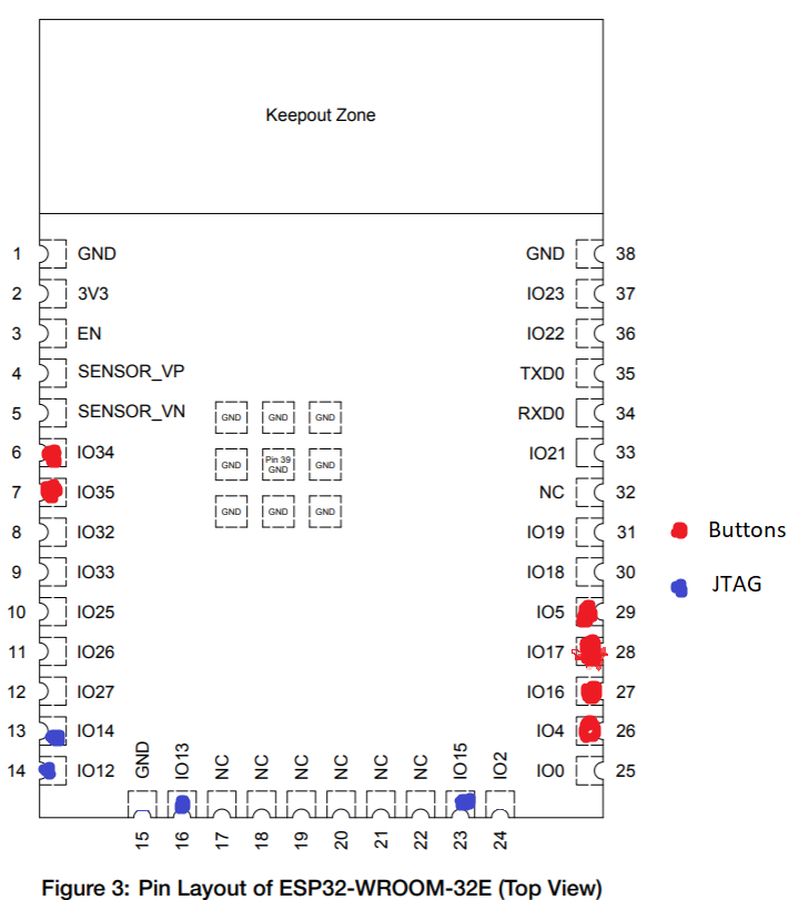
We already know we are working with an ESP32 chip, specifically ESP32-WROOM-32E.
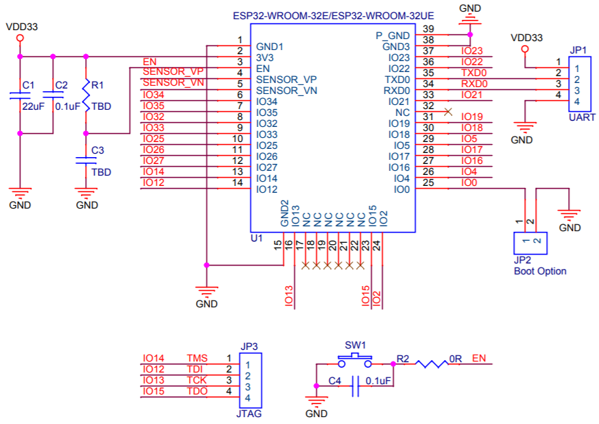
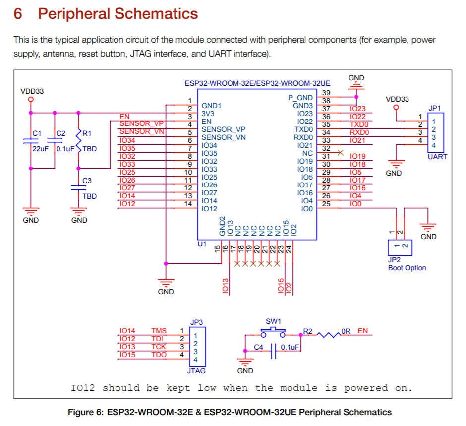
I started searching for the information and quickly found the chip's datasheet from the vendor. This started giving me a better understanding of the various GPIO pins on the chip with the full schematic.
Through some quick googling I initially thought I would need to leverage the badge's JTAG interface as part of the overall RE efforts. This ended up not being the case, however allowed me to learn a bit more about the hardware, and JTAG in general.
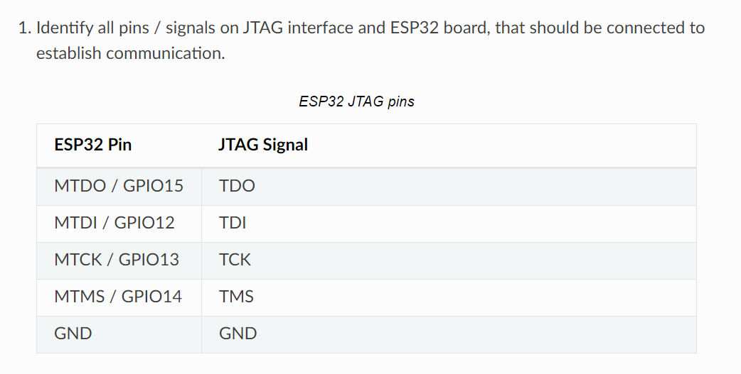
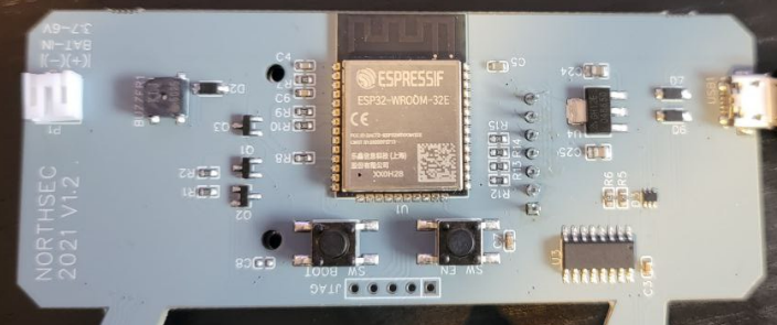
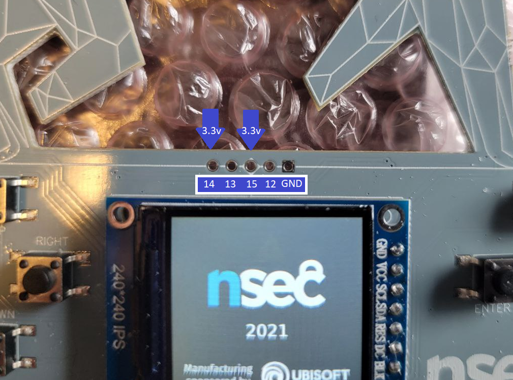
Following the traces on the board I was able to map the initial button and JTAG connections. This also gave me an excuse to break out the multimeter for the first time in years. Based on the spec sheet I could confirm which ports were high/low. While not necessary to continue it ended up being useful later on when trying to figure out bootloader options.
Firmware Dumping
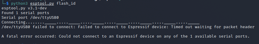
It was around this point that I ran into esptool - which describes itself as:
A Python-based, open source, platform independent, utility to communicate with the ROM bootloader in Espressif ESP8266 & ESP32 series chips.
Well that seems like something we might want to use. Based on the documentation this would allow us to work with the bootloader over the UART (serial) connection rather than having to create/get a JTAG interface for the board - sounds good!
Enter a bit of lacking knowledge, but further learning. When I got esptool setup and tried interfacing with the badge it didn't seem to be working. It would just time out and throw errors.
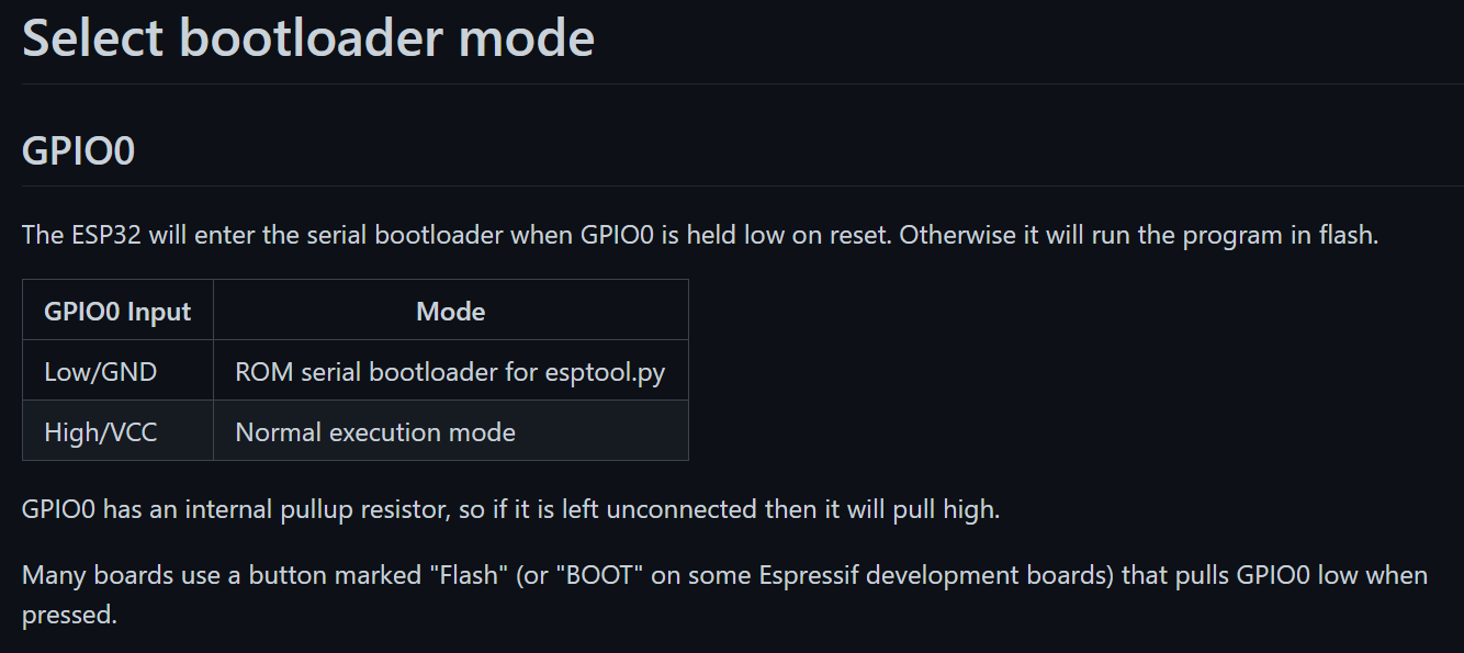
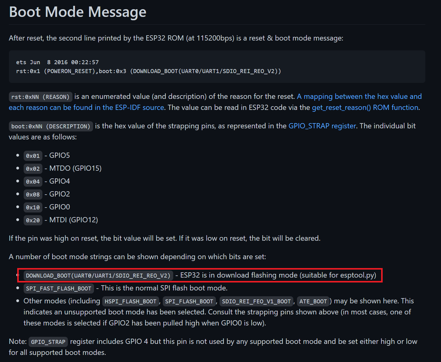
Alright back to the documentation. I quickly found something that seemed interesting.
If you look at the back of the board we have a BOOT button. Let's break out the multimeter and test out a few things. In addition to the multimeter I had the badge connected through the UART ports to capture any messages thrown.
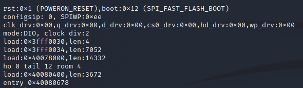
When just pressing the SW EN reset button, sure enough GPIO 0 was high and we see a normal flash boot entered.
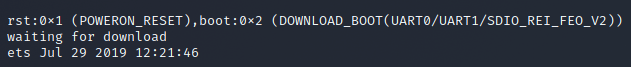
Next up, holding down the BOOT button while pressing SW EN we do see GPIO 0 go low, and subsequently see the badge enter bootloader.
Awesome! Now all that's left is to kick off esptool while it's bootloader! Right? Maybe? Maybe not...
Try as I might even when in bootloader mode I wasn't able to get esptool to work with the badge. Even the documentation itself was telling me this should be working.
What took me way too long to realize was that I needed to pull GPIO 0 low only when trying to connect with esptool directly. So it didnt matter if I had previously put it into bootloader, when executing esptool.py I needed to press the BOOT button.
Bonus Flag
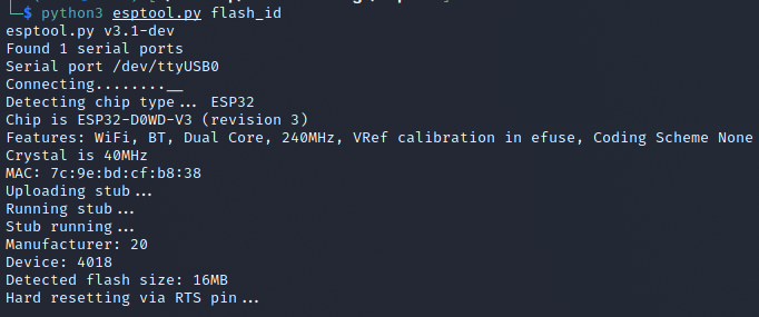
With the knowledge that our flash size is 16MB we can now proceed to dump the full firmware. This took several attempts and was painfully slow, but eventually I was able to get it completed.
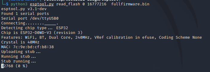
You can set the offset and length that you want to read. Instead of dumping the full firmware it was easy enough to swap those values based on partition information we will see below. I ended up going this route heavily since I would often run into memory corruption issues while trying to dump flash. Similarly esptool has a write_flash capability with the same offset and length arguments to determine where on the badge's firmware the passed binary should be stored. We will keep this in mind for later.
Before doing anything fancy with the firmware I ran a quick strings to see if we could pull out anything useful. Sure enough the bonus flag was right there for use to claim with flagbot on discord.
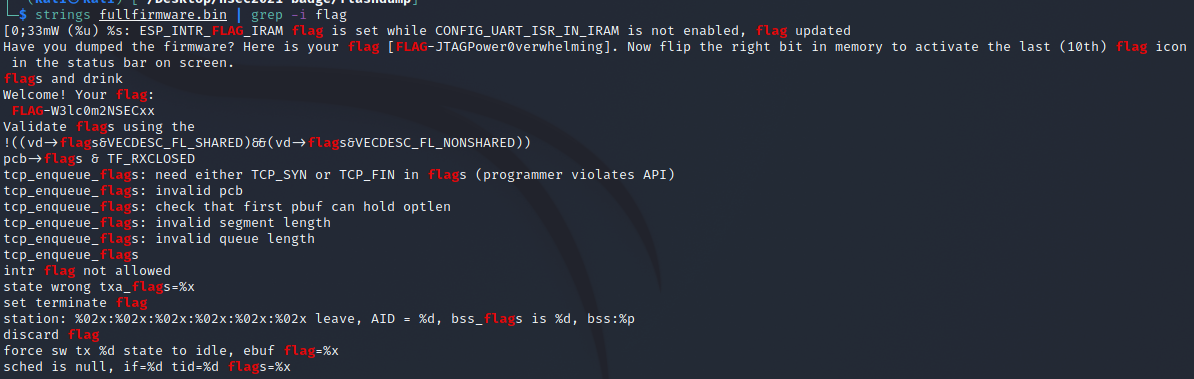
With the bonus flag captured, the full firmware dumped, and a reinvigorated drive to figure out how to flip that last flag (taunt me much with that line?) it's time to go even further.
Partition Investigation
We need to understand a bit more about the firmware before we can proceed. I mentioned above that when connected to the serial port and we go through a reboot cycle we are presented with some useful information - such as the specific boot mode. In addition to that however we are given much more information on the firmware itself.
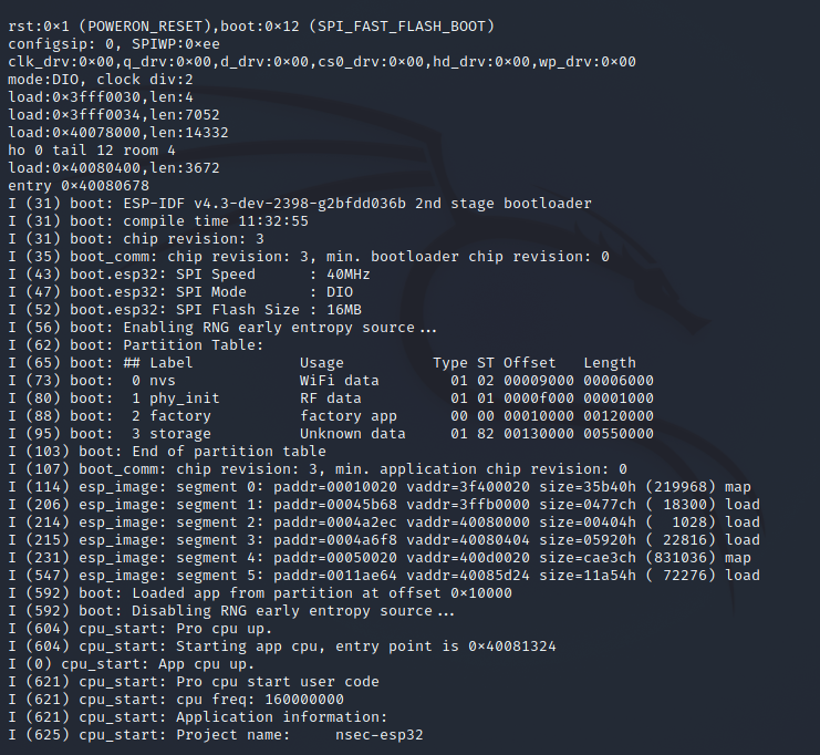
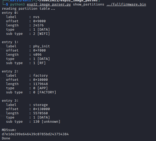
This gives us a good breakdown that there are 4 partitions: nvs, phy_init, factory, and storage. I ended up doing a bit of reading on the ESP32 partition tables to understand what these could be.
I quickly figured out that factory was our game's main code, storage was a SPIFF filesystem most likely containing supporting media (confirmed if you check the first article), which leaves us with NVS and phy_init. The documentation here mentions loosely:
There are also two data regions defined in the partition table for storing NVS library partition and PHY init data.
Which doesn't make too much sense just yet but we will table it for later.
Game ELF Reconstruction
This entire section was not required for the ultimate 10th flag manipulation, however at this point I had not gotten all the main flags yet and was hoping that using the factory_app partition and putting it through something like Ghidra could provide clarity. Unfortunately that wasn't the case, however I learned a couple more things about the ESP32 architecture as a result.
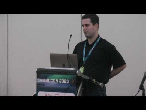
I had already carved out the factory_app partition from the full firmware and imported it to Ghidra. It was a mess trying to go through anything and I tabled that effort until I saw the following Shmoocon 2020 video.
As a quick, interesting sidenote, when I initially found this video it only had ~300 views, despite being published back in March 2020. In the last couple weeks that view count has more than doubled at time of writting this article. I wonder how many of those views were NSEC badge owners...
Very interesting stuff! The first thing I did after watching the video was to run a hexdump on the NVS partition and confirm that sure enough, my wifi details were right there in plaintext. Ugly ugly stuff considering how prevalent this chip is seemingly used.
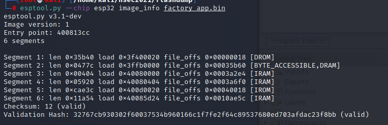
Back on topic of the badge I took a look at the partition's information using esptool.
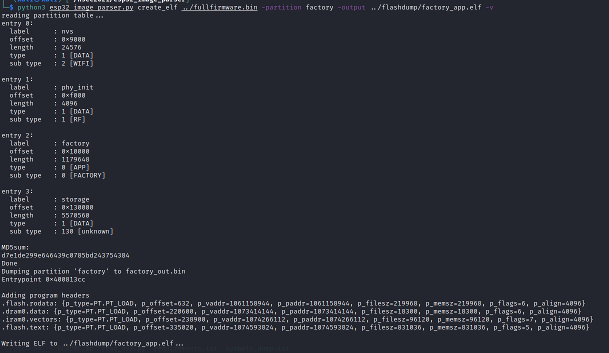
At this point I went and grabbed a copy of Tenable's esp32_image_parser and started playing around with what I could do. Let's try listing the partitions on our full dump.
So far so good. But when I tried to recreate an ELF from the factory_app partition I ran into a code issue.
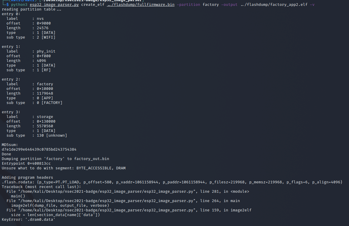
Looking at the code dram0.data is configured... what's the issue? If you look at the esptool image_info output you can see the mapping is slightly off. Tenable's code only addresses "BYTE_ACCESSIBLE, DRAM, DMA", however our badge has a dram0.data of "BYTE_ACCESSIBLE, DRAM". Let's add a section_map to match our configuration.
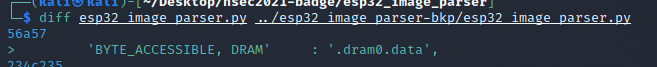
And sure enough this time it ended up working.
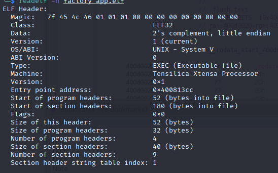
At this point I was able to load the ELF into Ghidra and start poking around.
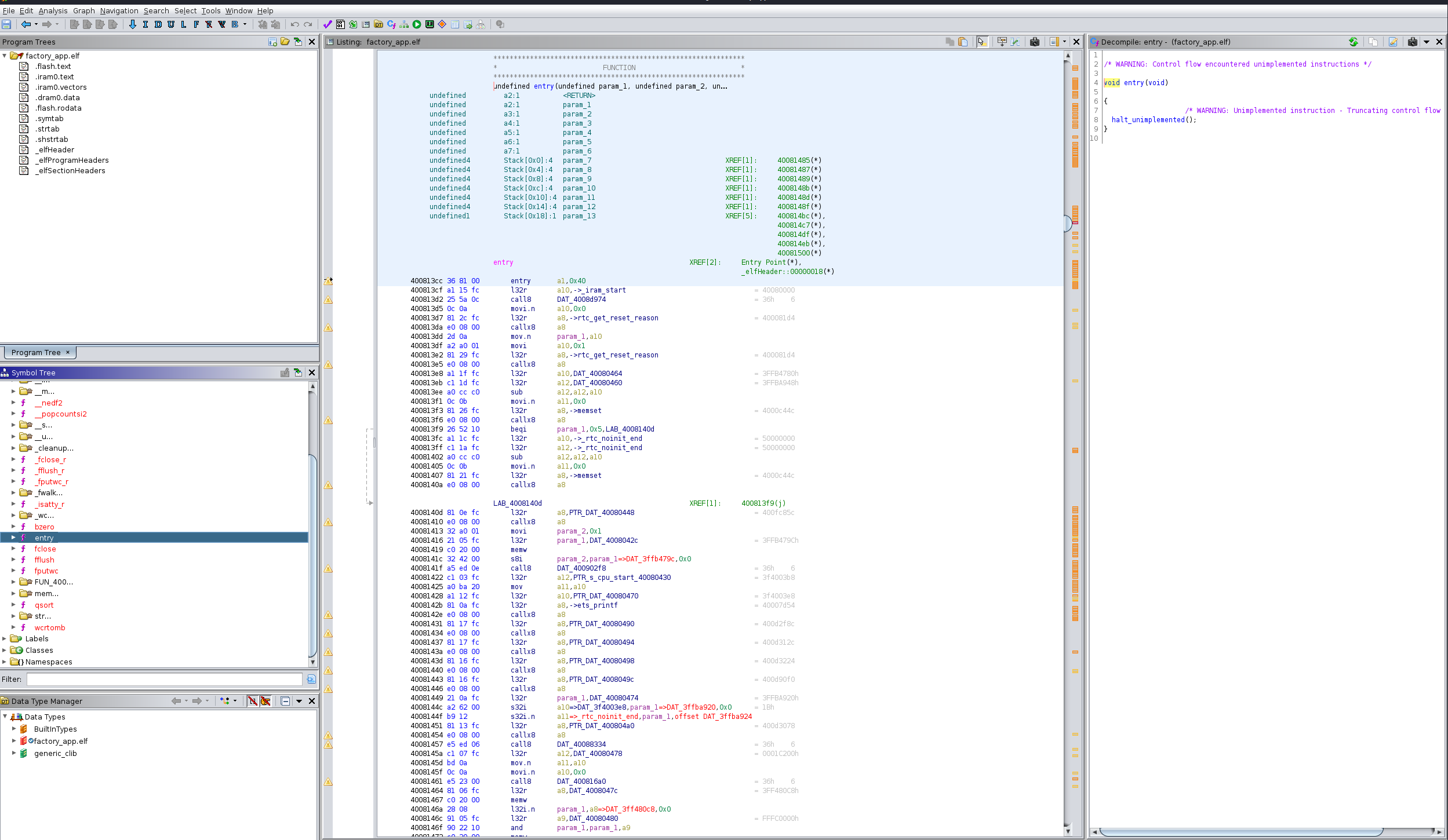
Sadly I still have quite a bit to learn in the overall RE domain. I'll keep at it as a learning exercise however the extent of use the ELF ended up being was:
- Confirming certain aspects I already knew from captured flags
- Reinforcing that the NPCs in the castle had proper dialogue options, therefore there should be a way to get there
- Finding the “hidden” CLI cmd hint, that ended up being an unintended easter egg
While I was able to find a lot of interesting tidbits, I wasn't able to properly tie anything together. So let's take a step back and see if we can figure out something else on the 10th flag.
NVS Partition Investigation
One thing I hadn't really thought about until now was the fact flags were persistent between power cycles. This means it's being stored somewhere. It wouldn't be in factory_app, as it's the core game code, and storage just has supporting media. This leaves us with phy_init and nvs. A quick hexdump look at phy_init quickly discounts this partition, so we are down to NVS.
Well back to the NVS docs. After a quick perusal I started understanding that the partition was essentially just a series of key-value pairs. Maybe one of those pairs ends up being our flag set?
Now what ensued for me was actually a happy little accident. At this point in my adeventure I had dumped the firmware at around half of the flags captured, and currently I was only missing 9 (and clearly 10). This allowed me an opportunity to dump the NVS partition and to do some cursory digging into the deltas. Sadly this wasn't very clean and the delta was quite massive. With several backups available I decided to try and take a stab at modifying the NVS partition and flashing it back on to the badge.

Unsurprisingly my attempt did not end up working - go figure. In fact instead of adding the missing flags this actually reset all the progress! This ended up being key to my investigation however as now I had a blank slate to work with. I quickly dumped the NVS partition of this "factory reset" version and pondered my next move.
I decided to go through every flag I had captured at this point, one-by-one, dumping the firmware between attempts. Trying my best to avoid any extra actions that could pollute the save state I managed to quickly get back to my previous progress state.
I then compared the first three states - blank, first flag, second flag, to see what it looked like.
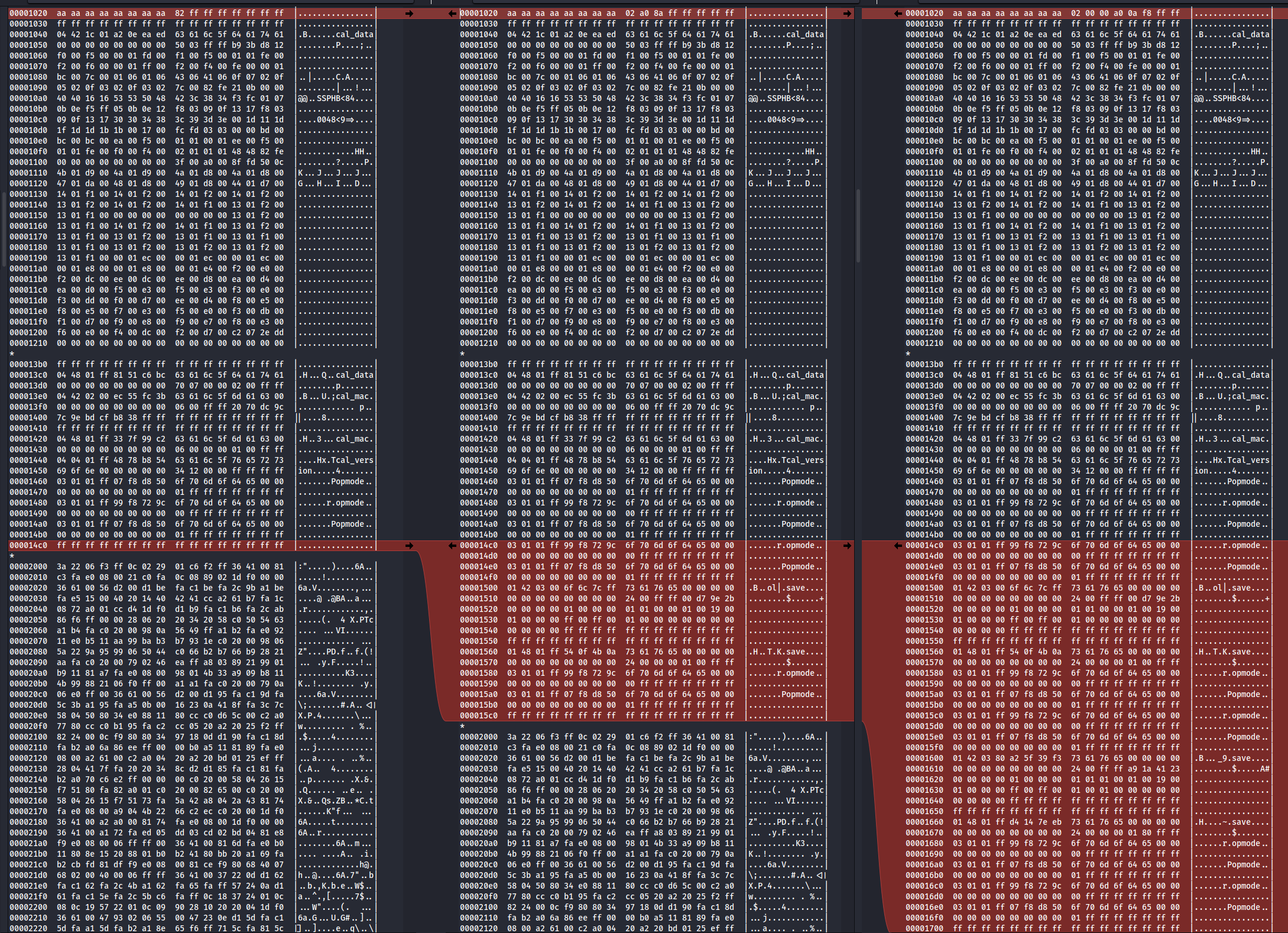
We can clearly see "save" in the deltas and it is seemingly growing after each flag. Very interesting...
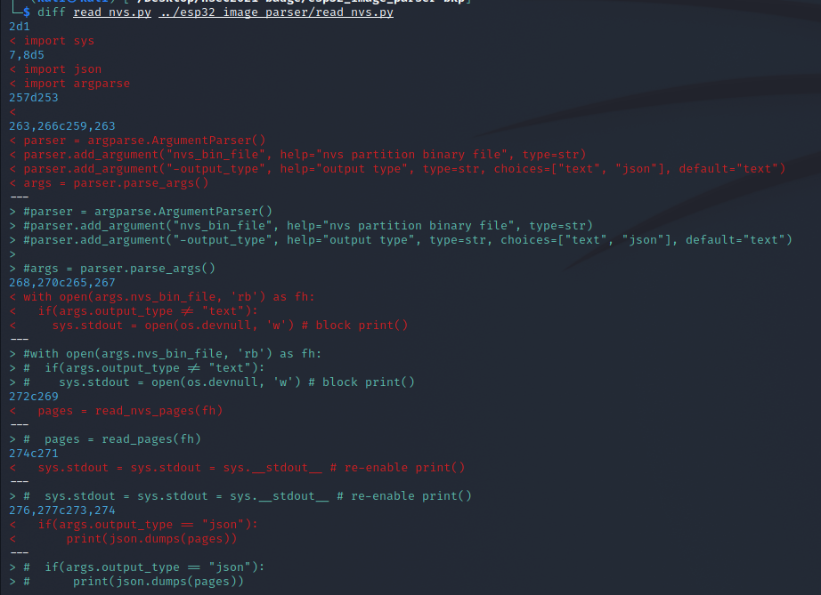
NVS Read
Since the NVS partition is just a storage of key-pairs there must be a way to read them. esp32_image_parser has a nifty utility called nvs_read.py that should do it. Unfortunately the state of the code at time of investigation was not usable. It seemed as if read_nvs.py started off as a standalone script, then was incorporated into the overall esp32_image_parser.py, and stopped halfway through the process. As a result, you could read the NVS partition from a full firmware dump, but couldn't use it on a carved out partition. With the amount of pain I had getting a full firmware dump I did not want to proceed that way so rebuilt read_nvs.py to be standalone and allow individual NVS partition reads.
Passing an NVS dump with a few captured flags I tried to find the "save" key-pairs we saw in the raw dump.
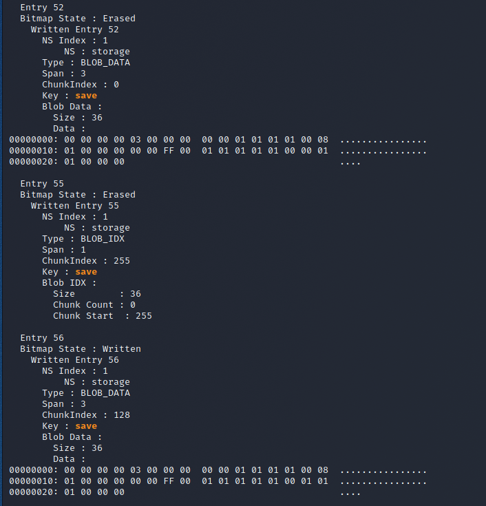
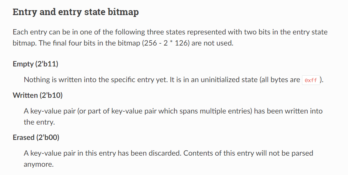
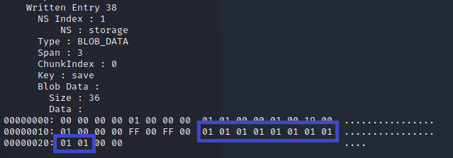
The last part we need to understand before being able to modify successfully goes back to NVS documentation. You'll notice above that there are multiple save key-pairs, with different data portions. The top one is Erased, while the bottom one is Written. This ends up being how NVS leverages its internal structure.
Firmware Modification
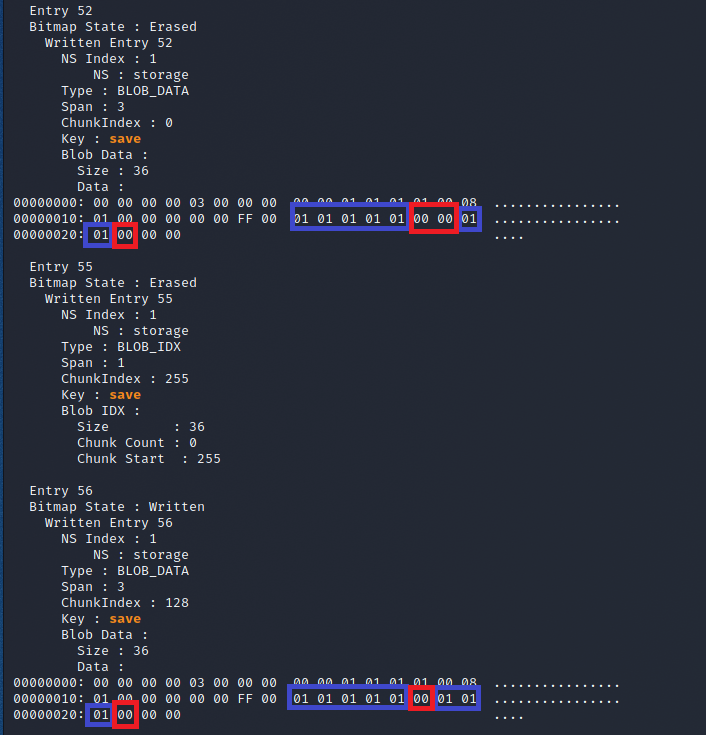
Alright so in theory we need to find the right save entry in NVS, which should be our "bitmap state: Written" entry and understand what needs to be modified as far as data.
To put into context I was missing flags 9 and 10, which translated to flag 6 and 10 on the UI (yes flagbot was a bit confused). The lightning strike so to say was when I compared the previous erased save data with the latest written data. You can see one additional bit was flipped. And the clincher is if you count which of the entries are 1 and 0, you can see that indeed the 6th and 10th pairs are left, which directly matches our missing flags! I now have a plan, hurray!
I quickly grabbed one of the copies of my NVS dumps, found where the written save entry was located and flipped the corresponding two bits.
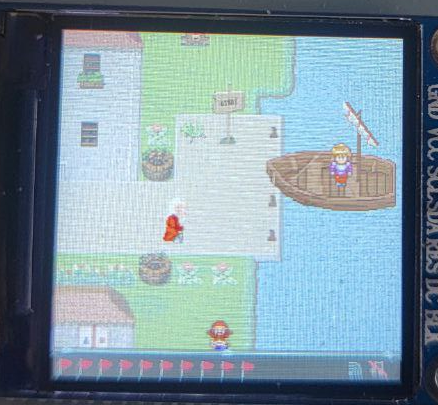
Then with a hope and a prayer I used esptool to flash the NVS partition back on to the badge. This time when entering the game I'm welcomed with a full flag bar!
Summary
Wow... just wow... what a journey. Considering when I started I hadn't even heard of an ESP32 chip before, the amount of documentation read, tools discovered, and just knowledge gained in general was crazy. I cannot be happier with my on-the-whim decision to order a badge to pass the time before NSEC 2021's CTF and I recommend to others on the fence to do themselves a favour and try it out.
I would be remiss to not mention Vicious and Tom from NSEC's dev team who helped keep our low amounts of sanity intact. In retrospect I can only laugh at some of the silliness they would have had to deal with from our end, and I thank them, and the entire NSEC team for doing so.
Additionally I want to thank Eric Hogue and Clayton for the conversations, sounding boards, tips and tricks, and generally just sharing the pain as we progressed through the various parts of the badge. I learned quite a bit and the conversations we had definitely contributed in no small part.
As always thanks folks, until next time!